How the improvement in the design of a traction motor pinion by SUPCO will prolong the pinion life span and reduce the maintenance costs of different types of traction motors.
When it comes to traction motor pinion gears, there is always a slight sliding or slipping on both sides of pitch point over tooth curvature. This sliding causes pitting and damages the traction motor pinion teeth, which as a consequence produces torsional vibration when rotating the gearwheel, and damaging the traction motor.
In this paper, SUPCO demonstrates the root cause of such damages and proposes a method for how to improve the traction motor pinions. Contact SUPCO for more information on traction motors.
Contact our experts
Don’t hesitate to contact us!
In This Article You Will Read:
- An Intruduction to Locomotive traction motor Pinion
- Chalanges in designing Traction Motor Pinion Gears
- How SUPCO overcame the chalanges faced in designing Traction Motor Pinion Gears :
- Further Improvement in designing traction motor pinion:
- Appendix A Involute Curve:
- About SUPCO
- References
An Intruduction to Locomotive traction motor Pinion
Transmission of rotational force from one axle to the other has a long history by using pulley and belt. This is still in use for many applications. However, when there is a high amplitude of force then due to tangential traction between belt and pulley, and limited fraction counterforce, slipping between locomotive traction motor pinion gear will be the main issue. Clip 1.
Therefore, an alternative means of transmission such as spur gear is to be utilized.
Clip1 – Pulley and Belt
As the case is in locomotives, where the traction motors are driving the locomotive’s axle through axle-gears. Spur gear transmission transfers force from locomotive traction motor’s pinion to axle gear as Normal force to the gear’s teeth compare to tangential force between pully and belt, so direct push will be applied by meshing 2 gears. See Clip 2
Clip 2 – Spur mesh gears
Replacing pullies by meshing gears, and string by engaging pinion and axle gear’s teeth. One should study the correct section of engaging teeth to have a constant velocity ratio while these 2 teeth are touching and passing one over another, see Fig 3, and video clip 2

Fig 3
The experiment on video clip 5 shows how such curve called as involute can be generated. To trace this curve, we locate a pen at point P on this string to draw the tooth profile for each pulley.
The planes where these two profiles are drawing on, is bond to the surface of their own pulley, as a rigid part turning together. For better understanding the 2 profiles generated, here on this clip are shown again on Fig 8 of the next.
Clip 5
Chalanges in designing Traction Motor Pinion Gears
Since both Involute sections are generated simultaneously at common point P , they constitute the shape of the 2 engaging tooth , having contact at pitch point P .
This is the point where the tooth on driving gear or pinion is touching the opposite tooth on driven gear installed over locomotive’s axle.
Within a short period of time, when the 2 opposite teeth are meshed, this touching or pitch point is tracing these 2 wedding profiles.
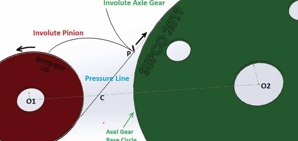
Fig 6
moving along 3 different paths depending on the plane in which the pen on point p is sketching on, Fig 6 :
- 1Lower involute generated by red pulley .
- 2Upper involute generated by Green pulley.
- 3The straight line tangent to both pulleys is called line of action or pressure line .
Clip 5 on previous page , shows how these profiles are generating
At the first stage, the involute generated by axle gear growing faster before reaching pitch point C (See Fig 6, and Fig 7 A ) so the slides passing the second involute generated by traction motor pinion gear, at the single point where the tangent point of the 2 Pitch circles, these two involutes have the same speed, so there is no sliding.
Then at the third stage, after passing the pitch point, the involute generated by pinion grows faster and slides passing over the involute produced by axle gear.
So there is always sliding in both sides of the pitch point. Consequently, the optimum tooth curve is the small segment at 2 sides of the pitch point, called Addendum and Dedendum sections.
Even small, but sliding always happens in 2 opposite directions around pitch point in locomotive traction motor pinion gear, during tooth engagement.
This continues and alternating slide during rotation and torque transfer on tooth surface cause stress and wear on gear teeth, which eventually damages pinion and causes Torsional Vibration and Resonance.
This is the common failure for traction motor in locomotives, resulting in high maintenance cost and revenue loss due to locomotive service downtime. Fig 7, A , B, and C illustrate how such sliding affects the cast of pinion tooth on Dedendum, pitch point and Addendum section.
As shown in Fig 7, A, and C pitting happens at 2 sides of pitch point due to surface sliding over each other.


After a certain duration of operation, the gear wear and tooth cast caused by sliding is inevitable see Fig 7 D.
Such phenomena in Locomotive traction motor Pinions is the subject of many studies by different institutes and laboratories under TRIBOLOGY.
In General, Tribology is the science of interacting surfaces relative to motion, including friction, wear and lubrications, which eventually causes better design of spur gears, bearing, and etc.That is why the gear design and their manufacturing process should have certain criteria.
Fig 8 shows pitting and the gear wear along pitch line caused due to above mentioned phenomena


Fig 8 (Fig 8, Reference: by GE , GEK-35824)
Of course, there are other causes for gear wearing, such as lubrication issue, debris and gear misalignments.
Distance between the 2 gears is the sum of their Pitch Circle Radiuses, in this case it is 17.11″ see DWG 152-1234 of Appendix A. Each of these 2 involutes are a function of their Base Circle Diameter.
The parameters of involute equation, relation between Base circle and Pitch Circle Diameters, are described in Appendix A.
For this study, Part # EMD 9556211 as 19 teeth TM pinion, and Part # EMD 8486278 as 58 teeth axle gear on locomotive axle are chosen. Although, there are many other types of gears , but the principles are the same.
How SUPCO overcame the chalanges faced in designing Traction Motor Pinion Gears :
To overcome mentioned issues on pinion, and the costs on Traction Motors repairs, as a result of faulty pinions , the material or steel alloy for manufacturing and the process of manufacturing has a significant impact on the quality of pinion, the manufacturing process mainly include carburizing/Decarburizing process, and case hardening are the 2 main important factors for a qualified Pinion, see section 6 Reference Standard, ASTM, 837, and EMS 157.
In supplying pinions to its clients, SUPCO has the necessary information and technical experience for how to assess the manufacturer facilities, test and quality control the pinion received from its vendors and manufacturers.
Further, SUPCO in its consulting project helps the clients verify the root cause of defective locomotive pinions, and advise the best way to solve the problem.
Case hardening produces a very hard gear tooth surface which is more wear resistant compared to gearing made in the past.
Carburizing and hardening is done in Quench Furnace, or by induction. As per technical condition, Bore and Threads should be free from case so we do heat treatment in two steps:
- 1 Only carburizing operation after teeth cutting and rough machining keeping sufficient machining margin more than total case depth i.e. 2.5 mm. in bore & thread portion dia O 4.939′ .
- 2After carburizing, we remove the case of bore and O 4.938″portion, where threads must be cut keeping machining and grinding allowances.
Hardening & Tempering :
After doing above operation, finally the material is sent for hardening & Tempering.
Cycle of plain carburizing:
Preheating is done up to 450″ C and kept for one hour (Soaking time) then heat up 940″C i.e.
at austenizing temperature, and kept for 2 hours under CP 1.5 I, then it is boosted for t hours for 2.5 mm cast depth. Then we defuse it for 4 hours minimum * soak for t hours then we refrigerate it in furnace up to 520″C + then take out from the furnace and wait until it gets cooler it in the air .
When we check the hardness, it is understood that it has achieved 26 to 28 HRC, which is compatible with the machine.
After bore machining & thread cutting , we send it for hardening and tempering.
Cycle of hardening and tempering :
- 1 Hardening Cycle: Preheating up to 450″C and kept for one hour (Soaking time) . Then heat up to hardening temperature. 870″C and kept for 2 hours (for homogenization ) . Then quench in agitated quenching oil (oil temperature 50″C) ) kept in quenching tank for 20 to 25 minutes.
- 2Tempering Cycle: Heat up to 180″€ and kept for 2 hours, then we wait until it gets cool in air.
View Supco products
Further Improvement in designing traction motor pinion:
This section will be updated in the future.
Appendix A Involute Curve:
Appendix A Involute Curve
To study the equation of an involute section and for simplicity, let’s consider a pulley fixed over a horizontal plane with a string wounded around it, see clip 9.
By unwinding this string from pulley, The front end of this string will trace a curve over this horizontal plane called involute.
Click clip 9 to see how an involute is generated. As the string is unwinding by angle “q”, its length is increasing by “DL” which is proportion to , see fig 10 .
Where L = R*q/2 is the opened section of the string, R is the radius of this pulley, called Base Circle radius or half of Base Circle Diameter which is the same circle in gear case, and q in radian is the angle of opened string.
The Base Circle Diameter BCD, in gears is equal to Pitch Circle Diameter PCD multiplied by “Phi” or Pressure Angel.

The pressure angle is the angle at pitch point between the line of pressure (which is normal to the tooth surface), and the line tangent to the pitch circle, or the angle between:
a) The line tangent to both pulley’s Base Circle, and b) The line perpendicular to the line passing through motor pinion gears’ centers, see Fig 11.
The pressure angles are usually 20 or 14.5 degrees; BCD=Phi * PCD.
The distance between gears are the sum of 2 Base Circle Dia, which for our case is 17.11″, see DWG 154-1234

Fig 11
The Polar equation of involute curve can easily be driven from the experiment mentioned in Clip 9, and Fig 10, as the polar coordination of string front end ;

Key Figures
- Pinion 19 teeth, EMD 9556211
N = 19 Number of teeth
P = 2.25 Diametral Pitch (Base Dia. Inch / N), or Modul= (N / Base Dia. mm) = 11.288
Phi = 20 Deg. Pressure angle
dp = N/P = 19/2.25 = 8.4444″ or dp= N * Module = 19 * 11.288 = 214.488 mm , 8.444″, Pitch diameter
db = dp * Cos(PHI) = 8.4444 * Cos(20) = 7.935″ , Base diameter
- Axle gear 58 teeth, EMD 40049658, 8486278
N = 58 Number of teeth
P = 2.25 Diametral Pitch ( Base Dia. Inch / N ), or Modul= (N / Base Dia. mm) = 11.288
Phi = 20 Deg. Pressure angle
dp = N/P = 19/2.25 = 25.778″ or dp = N * Module = 58 * 11.288 = 654.736 mm , 25.778″, Pitch diameter
db = dp * Cos(PHI) = 8.4444 * Cos(20)= 7.935″, Base diameter
Center to Center Dimension = dp (19) / 2 + dp (58) / 2 = 8.444/2 + 25.778″/2 = 17.111″
About SUPCO
SUPCO is a company that is producing and exporting Traction Motor Pinion Gears. It includes experts from different branches of Locomotive designing to establish a potential atmosphere for competition in order to create the most qualified Locomotive Traction Motors.
Our company is a highly dependable compound for the best North American producers, which offers a long-term relationship and gives after-sale services to customers.
To see our products, more information on traction motor pinion visit the Traction Motor Products page on our website.
Also, check other articles on our blog for different types of traction motors and details of AC vs DC traction motors.
For more advice on purchasing locomotive traction motor parts, contact SUPCO via this link:
Contact our experts
Don’t hesitate to contact us!
References:
- EMD Material Spec. SISI – 8620H for Carburized Alloy Steel.
- ASTM Standard A 837/A. 837 M Steel for Carburizing application.
- EMD Material Specification EMS 0157, Steel for Carburized Application, Axle gear, ASTM A534
- GE Inspection report on locomotive Traction Motor Pinion gear, GEK 35824
- Tribology in Machine Design, by Dr. Stolarski